15.2.1 Preparation of the SX2 QuadBRI before insertion
The ISDN card (SX2 QuadBRI or SX2-express DualPRI) has to be configured with jumpers and DIP switches before can be installed into the computer.
The operating mode (TE/NT) and the bus termination must be configured for each line of the SX2 QuadBRI or SX2-express DualPRI before insertion.
Requirement for further description: Requirement for further description: The SX2 QuadBRI or SX2-express DualPRI is directly in front of you, with the PCI plug strip facing down and the S0 connections to the left.
Configuration of the Operating Mode
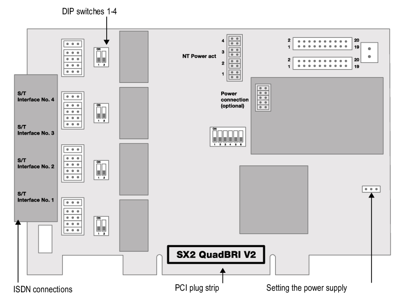
Each BRI bus connection is a jumper block with five assigned jumpers. If all five jumpers are inserted to the left, the connection is configured as NT. If all five jumpers are on the right-hand side of the block, the connection is configured as TE. So on one board some connections can operate in NT mode and other in TE mode at the same time.
All five jumpers of one block must have the same position, e.g. all facing to the right, or all facing to the left.
After the installation of the driver software, the same operating type must be set in the configuration dialog. It is therefore not sufficient to configure the operating mode on the hardware only or in the software only.
Configuration of the supply voltage in NT mode
An interface configured for NT mode can be fed with 40V from an optional external feed module. Connect this feed module to the green connector on the upper right side of the SX2 QuadBRI or SX2-express DualPRI.
Using the SX2 QuadBRI V2 with an external feed module you have to insert additionally the two outer jumpers on the plug-in slot of the internal feed module (see figure below).
For each NT interface to be fed, set two jumpers for each port to which you want to supply power. Afterwards, ISDN devices that are intended for supply from the public line can also be operated directly on the SX2 QuadBRI V2 or SX2-express DualPRI.
Please ensure that you use the feed module only for interfaces that are configured for NT mode, Otherwise the interface will be damaged.
Alternatively, you can mount an internal feed module directly on the SX2 Quad-BRI.
Do not use an internal and an external feed module at the same time.
Configuration of the SO bus termination
Next to the block of jumpers for a connection, you will find a two-pole DIP switch which can be used to configure the BRI bus terminal.
 If both pins of the switch are in the "ON" position, the 100ohm terminal is switched on, otherwise it is switched off.
Both pins must have the same setting.
Configuration of the PCI bus power supply (not for SX2-express DualPRI)
On the right side of the SX2 QuadBRI is a three-pole jumper field for setting the PCI bus power supply.
Make sure that the jumper is at the correct setting for the computer's main board.
Left ("3V3 reg") for an environment with 5V, right for an environment with 3.3V, which will be found on older main boards.
Configuration of the card number
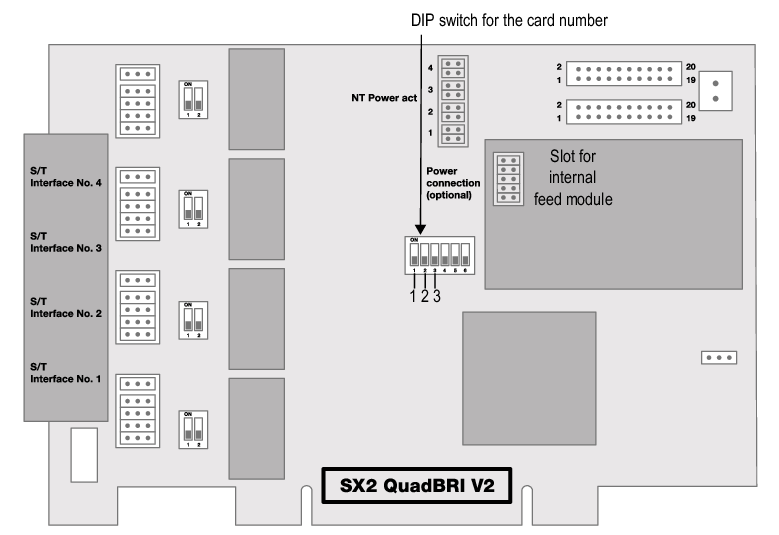
You can set the card number with the six-pole DIP switch in the middle of the SX2 QuadBRI.
SX2 QuadBRI V2

For SX2 QuadBRI V2 the following assignment is valid:
Switch 1 | Switch 2 | Switch 3 | Card number |
|---|---|---|---|
off | off | on | 1 |
off | on | off | 2 |
off | on | on | 3 |
on | off | off | 4 |
on | off | on | 5 |
on | on | off | 6 |
on | on | on | 7 |
off | off | off | assigned automatically |
If you use several cards in one system, please make sure that either one card number was assigned for all cards, or automatic card number assignment is set for all cards.
SX2-express DualPRI

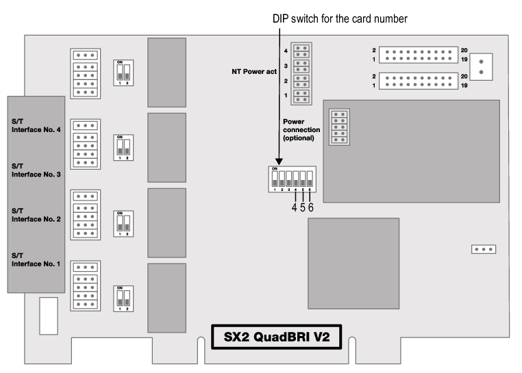
Fig. 15-1: Card number configuration of SX2-express DualPRI
For SX2-express DualPRI, another assignment is valid:
Switch 4 | Switch 5 | Switch 6 | Card number |
|---|---|---|---|
on | off | off | 1 |
off | on | off | 2 |
on | on | off | 3 |
off | off | on | 4 |
on | off | on | 5 |
off | on | on | 6 |
on | on | on | 7 |
off | off | off | assigned automatically |
If you use several cards in one system, please make sure that either one card number was assigned for all cards, or automatic card number assignment is set for all cards.
PCM bus connection
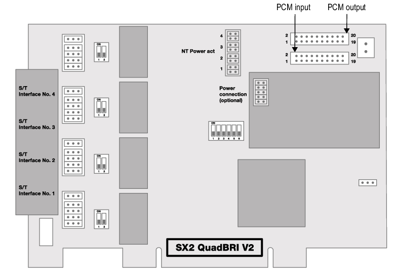
The SX2 QuadBRI / SX2-express DualPRI has two 20-pole jacks for connection with an optional PCM cable.

Fig. 15-2: PCM connection of SX2-express DualPRI
The upper jack is the output, the lower jack the input. Connect the SX2 cards with the PCM cable, by connecting the output jack of one card to the input jack of another card.
Please keep in mind that the connection cable differs between both SX2 boards ( SX2 QuadBRI or SX2-express DualPRI). A mixed operation using both card types in one computer is not supported.
LED Status Display
To each BRI connection one of the four LEDs is assigned.. The number of the connection corresponds to the number of the LED.
The following illustration shows a slot of the SX2 QuadBRI to identify the Basic Rate Interfaces 1 to 4, shown here as L(ine) 1 to 4:
Fig. 15-3: Lines of the SX2 QuadBRI
The following assignments are valid:
LED | Statement |
|---|---|
off | Layer 1 deactivated |
red glowing | Layer 1 activated |
green glowing | Layer 2 activated |
green, blinking | At least one connection is active |
red, blinking | The line is being configured |
After the hardware for the SX2 QuadBRI has been configured according to the use scenario, insert it into the computer on which SwyxGate is to be installed.
After the card has been installed physically, it will automatically be recognized the next time the computer is booted and a request for the installation of the driver software will appear.